The Build:


Block Diagram:


images/45-1.png

As-built Hardware:


Ground system: 8ft ground rod + 36 1/2 wave radials
1/4 wave Vertical 20m antenna
Lightning arrestor (static drain)
Narda SEM143DT 4 position Coaxial Switch
Nano PI Neo Single Board Computer (SBC)
5 port Ethernet Switch (SBC does not have strong enough line drivers for 150ft ethernet run)
28v to 5v potted buck converter (origin unknown)
Material 31 Ferrite choke (reduces noise from buck converter on SDR reciever)
Standard 6" Cantex Project box
Steel wool (keeps the mice out)
images/45-2.pngimages/45-3.pngimages/45-4.png


As-Built Software (Interfaceing with the Coaxial Switch):


First off, why a coaxial switch? Because my 500w transmit antenna is only about 100ft away
It wrecks the reciever input. Thus I now switch to the mini-antenna when transmitting
Here's and example of my unattenuated transmit signal into the WebSDR at just 35w:

images/45-5.png

Currently the coaxial switch is controlled via a software interface I wrote. I later intend to
link it to the key circuit for the amp so its automatic and not manual.

The interface is a simple Command Line Interface (CLI) for switching the Antenna ON/OFF/Attenuated
The attenuated signal is running through the small antenna that i switch to when transmitting

This CLI is not available to WebSDR users
images/45-6.png


Here is the source code I wrote for that CLI:
//                     HELPFULL PIN MAPPING AND FUNCTION DIAGRAM
//
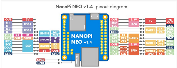
//        SW PIN                       HW PIN                         SW PIN
// +-----+-----+----------+------+---+-NanoPi-NEO--+------+----------+-----+-----+
// | BCM | wPi |   Name   | Mode | V | Physical | V | Mode | Name     | wPi | BCM |
// +-----+-----+----------+------+---+----++----+---+------+----------+-----+-----+
// |     |     |     3.3V |      |   |  1 || 2  |   |      | 5V       |     |     |
// |  12 |   8 |  GPIOA12 |  OUT | 1 |  3 || 4  |   |      | 5V       |     |     |
// |  11 |   9 |  GPIOA11 | ALT5 | 0 |  5 || 6  |   |      | 0v       |     |     |
// | 203 |   7 |  GPIOG11 |  OUT | 0 |  7 || 8  | 0 | ALT5 | GPIOG6   | 15  | 198 |
// |     |     |       0v |      |   |  9 || 10 | 0 | ALT5 | GPIOG7   | 16  | 199 |
// |   0 |   0 |   GPIOA0 | ALT5 | 0 | 11 || 12 | 1 |  OUT | GPIOA6   | 1   | 6   |
// |   2 |   2 |   GPIOA2 |  OFF | 0 | 13 || 14 |   |      | 0v       |     |     |
// |   3 |   3 |   GPIOA3 |  OFF | 0 | 15 || 16 | 0 |  OFF | GPIOG8   | 4   | 200 |
// |     |     |     3.3v |      |   | 17 || 18 | 0 |  OFF | GPIOG9   | 5   | 201 |
// |  64 |  12 |   GPIOC0 |  OUT | 1 | 19 || 20 |   |      | 0v       |     |     |
// |  65 |  13 |   GPIOC1 |  OUT | 0 | 21 || 22 | 0 | ALT5 | GPIOA1   | 6   | 1   |
// |  66 |  14 |   GPIOC2 | ALT4 | 0 | 23 || 24 | 1 |  OUT | GPIOC3   | 10  | 67  |
// +-----+-----+----------+------+---+----++----+---+------+----------+-----+-----+

#include <stdlib.h>
#include <wiringPi.h>
#define RESET "\033[0m"
#define GREEN "\033[32m"

int main(void)
{
  int input ;
  int z = 0 ;
  char a[100] = "Nothing" ;
  
  wiringPiSetup() ;
  pinMode (7, OUTPUT) ;
  for(;;)
  {
   system("clear");
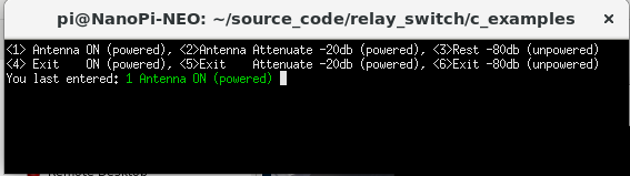
   printf("<1> Antenna ON (powered), <2> Antenna Attenuate -20db (powered), <3> Rest -80db (unpowered) \n");
   printf("<4> Exit    ON (powered), <5> Exit    Attenuate -20db (powered), <6> Exit -80db (unpowered) \n");
   printf("You last entered: " GREEN "%i %s " RESET, z, a) ;
   scanf("%d", &input);
        if (input == 1)
        {
                z = 1 ;
                strcpy( a, "Antenna ON (powered)") ;
                digitalWrite(7, HIGH) ;
                digitalWrite(1,  LOW) ;
        }
        else if (input == 2)
        {
                z = 2 ;
                strcpy( a, "Antenna Attenuate -20db (powered)") ;
                digitalWrite(7,  LOW) ;
                digitalWrite(1, HIGH) ;
        }
        else if (input == 3)
        {
                z = 3 ;
                strcpy( a, "Rest -80db (unpowered)") ;
                digitalWrite(7,  LOW) ;
                digitalWrite(1, LOW) ;
        }
        else if (input == 4)
        {
                printf( GREEN "EXIT Antenna ON (powered)\n" RESET);
                digitalWrite(7, HIGH) ;
                digitalWrite(1,  LOW) ;
                return 0;
        }
        else if (input == 5)
        {
                printf( GREEN "EXIT Antenna Attenuate -20db (powered)\n" RESET);
                digitalWrite(7,  LOW) ;
                digitalWrite(1, HIGH) ;
                return 0;
        }
        else if (input == 6)
        {
                printf( GREEN "EXIT Rest -80db (unpowered)\n" RESET);
                digitalWrite(7,  LOW) ;
                digitalWrite(1, LOW) ;
                return 0;
        }
  }
}


Nano PI neo gpio driver software for GPIO pin acces
https://github.com/friendlyarm/WiringNP

images/45-7.png

images/45-8.png

Hardware Coaxial Relay interface:


I used GPIO Pins 7 and 12 on the Single board computer. Here's the SBC pin out...
images/45-9.png

Highlights from coaxial relay data sheet
images/45-10.png


images/45-11.png


Web SDR and special RTL_TCP drivers:


the RTL-SDR V3 software defined radio dongle typically samples from 70mhz to about 1.75Ghz.
However it can be put into direct sampleing mode in order to operate within the HF bands.
Since the reciever is remote from the interpolator (WebSDR software) the RTL_TCP driver was invoked to
send the RAW IQ stream over the LAN. To further complicate things, the standard driver
provided will not do direct sampling over TCP. A special branch of the driver was chosen
(there is more than one but i chose the excalibur driver).

THE SOURCE

for RTL_TCP direct sampling branch
https://github.com/bclswl0827/rtl-sdr (dont use this one, its buggy)

https://github.com/Excalibur201010/librtlsdr_direct_sp (USE THIS ONE!)

compile it with rules for non root usb dongel access


sudo apt-get install libusb-1.0-0-dev git cmake
git clone git://git.osmocom.org/rtl-sdr.git
cd rtl-sdr/
mkdir build
cd build
cmake ../ -DINSTALL_UDEV_RULES=ON
make
sudo make install
sudo cp ../rtl-sdr.rules /etc/udev/rules.d/
sudo ldconfig

The WebSDR software:


The WebSDR software package from the author is relativly easy to follow along with
He provides the compliled software package by request only.
The HTML portion of the software package is highly customizeable.
I modified it only slightly to allow concise user control and minimal fluff.

The original software was not designed for the RTL_SDR dongle but a special hardare SDR. Once I
realised this, things went rather smoothly.

Current Issues:


Coaxial relay is normally open type, it disspates 3 watts to hold the antena closed and connected
to the SDR. This heat is a problem.

The Buck converter I suspect, is still making some noise for the SDR, moving it back to the shack
and piping 28v and 5v DC over the ethernet may help receiver sensativity.

Between the out of band transmisions that get into the front end and the Signal Mirroring beyond
14.440Mhz I am considering adding a 20m band pass filter to the front end of the SDR receiver.

Thanks for stopping by...
KF7RCS
-73